Published by World Cement Magazine, February 2023 issue.
World Cement Magazine has been published since 1928. It is the leading monthly trade magazine covering the cement industry and circulated globally to an ABC-audited circulation of over 5000 key industry decision makers.
Zeki Özek, Özek Makina, offers some insight into inspecting and maintaining rotary kilns in a cement plant.
A rotary kiln is a tool for calcining thousands of tons of raw mix at temperatures of 1450˚C every day. This tool, of which almost all parts are made of steel, can reach a total weight of 1000 t when the refractory and the product inside are taken into account. Rotating such a large mass on relatively small rollers and protecting it from such high temperature is one of the greatest challenges facing production, which must continue 365 days a year.
The rotary kiln has a quite simple geometry. Each pier, consisting of a tyre and two rollers, is positioned to form an equilateral triangle between the tyre and roller centers. Each station is positioned to share the total load in a balanced way. The shell, which is made of a thick steel plate and covered with refractory bricks, passes through the tyre centers of these piers, and ensures the transformation of the raw material into clinker while transferring it.
The whole unit, which is installed with a slope that facilitates material transfer, works by rotating a girth gear mounted to the shell. So, the whole problem becomes simply to keep a few equilateral triangles aligned in space.
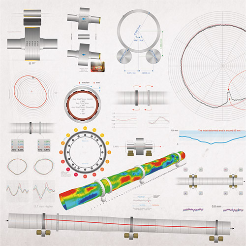
Visualisation of kiln inspection data.
It really is that simple on paper. But consider that the object in question is a steel tube with a diameter of 4 – 5 m and a length of 60 – 70 m, through which thousands of tons of material is transferred while reaching a temperature of 1450˚C.
The chemical reaction inside the kiln, the elastic deformation (ovality) of the shell, and the friction of the material passing through it seriously erodes and thins both the shell plate and the refractory. The temperature rising to different levels throughout the kiln causes the shell to bend temporarily or permanently. The thermal or mechanical crank-form shell rotation that occurs in this way creates dynamic load on the rollers of each pier which can reach up to several times the estimated design value. The girth gear starts to move closer and further away from the pinion by rotating with a significant run-out, and even hits the pinion gear tooth at advanced levels, causing serious vibration.
Meanwhile the rollers, which are skewed to push the kiln uphill, against the kiln slope, wears out in a conical surface form along with the tyres. The contact surfaces of tyres and rollers become narrower, the load and stress per unit area increase, and thus, surface scratches and cracks, as well as uneven, wavy abrasions on these surfaces are encountered frequently.
The axial movement cycle of the kiln, which loses its designed tyre/roller relation, is impaired. The pressure applied to the thrust roller increases, and eventually these surfaces cannot be freed from deformation.
On the other hand, the wobble of the tyres causes dynamic contact with the rollers and directly alters the roller’s effect on the kiln’s axial movement. The rollers move axially inside the bearings and warm up due to the friction of the thrust disc and the bearing.
The inspection
The generic name given to “a detailed technical inspection and measurement of the kiln, the analysis of these measurement results with strong foresight and experience, and the elimination of the resulting deviations by rearranging the roller positions” is hot kiln alignment.
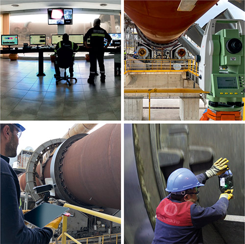
Several measurement setups.
In fact, the kiln rotates with the combination of the issues mentioned above. Some of these problems may be in their infancy. Some may have reached the level of increased bearing temperature, slight vibration in the pinion gear, a kiln that will not go down, or a significantly worn tyre or roller surface.
And some may have reached the level of the mechanical shell crank and dynamic roller load, which is about to stop the kiln.
The main goal is to detect and solve these problems before they stop operations. And this goal is the key to transform unexpected, large, and expensive maintenance into planned, relatively small, and inexpensive preventive maintenance.
In essence, kiln inspection studies include the precise measurement of detailed information such as the tyre and roller diameter; concave, convex, conical, or elliptical form developed on these surfaces; the distance between the roller centers; inclination of the rollers; thermal relation of the tyre and shell; the ovality of the shell; under-tyre clearance; the relative movement of the tyre; tyre wobbling value; and the current kiln axis from both top and elevation views. All measurements must be taken carefully with the help of precise equipment specially designed for this job.
For example, if the diameter of one of the rollers has reduced due to wear, the center of the tyre will shift towards the smaller roller and down. Or if one of the roller’s bearings is more worn, the roller inclination shifts and therefore its contact with the tyre will change. If the chairpads between the tyre and shell are worn out, the under-tyre clearance, the shell’s elastic deformation (ovality), and tyre wobbling will increase as a result, the lifespan of the refractory bricks’ will shorten, the tyre/roller contact is altered and therefore the kiln’s axial movements will be unstable. This list may expand with singular issues or complex problems that they create by triggering each other.
The analysis of all these inspections and measurement results can offer operators practical solutions such as the adjustment of one or more rollers, as well as relatively more complicated solutions such as changing a part of the shell, machining and grinding some of the tyres or rollers, changing the tyre, roller, its bearings, or the girth gear.
But even if the proposed solution is practical or complicated, it will pave the way for the kiln to continue to work healthily and efficiently for many years. This article will focus on the alignment and tyre/roller machining solutions.
Adjusting the axis and the axial movement
The alignment is basically necessary for solving three main problems. These solutions are placing a deviated station on the axis, relieving a roller experiencing heating on the thrust disc, or arranging the axial movement of the kiln.
Roller skewing for kiln alignment.
The axial deviation observed in the inspection results is usually resolved by pushing one or more rollers in or out in parallel in light of information such as girth/pinion gear relation, calculation of the current load on each roller, and determination of mechanical deformation of the shell.
If plats are having a temperature problem in one of the roller bearings, they must first determine whether it is due to the bearing/thrust disc or the bearing/shaft relation. The solution might be as simple as skewing the roller to gain some clearance between the bearing and the thrust disc or may lead to the replacement of a bearing or even a whole roller depending on how the heat is generated.
It means that operators may have to stop the kiln, cool it down, lift the tyre up, open the housings, take out the roller, replace the bearing with the new, carefully scrubbed one, replace all of the oil, place the roller back and fire the kiln, and finally wait until it is clear that the new bearing works properly.
Or it may just require the skewing of one of the rollers by half a millimeter to reduce its axial load and therefore relax the kiln’s axial cycle. But please keep in mind that this simple solution may turn into a complicated one since it

Roller, housing and chassis replacement.
requires touching the kiln’s axis and may easily affect the other rollers which are already at their limit. So, it is highly recommended to note all the rollers for their thrust disc gaps, analyze their contribution to the kiln’s axial movement and plan the next step after that.
It is strongly recommended to follow a professional report or supervisor during these works which sounds simple but might easily turn to a nightmare if not rendered carefully.
A kiln technician should make daily visits to the kiln and observe the main areas of concern carefully. These visits will help to develop an important awareness of the kiln, as well as to understand the differences that occur over time.
Although it is not possible to align the axis without a precise measurement, it is useful to be prepared to intervene in some emergency and minor situations such as bearing temperature or axial movement problems.
Machining and grinding the tyre and roller surfaces onsite
As mentioned earlier, the kiln is designed and installed with a certain inclination for a healthy flow of materials. A body of this mass, installed on an incline, cannot remain stationary without being fixed at any point. For this reason, the rollers are skewed to use the rotation of the body and give axial movement to the kiln, just as it occurs in a bolt. But the skew of the rollers should balance the kiln’s downhill force caused by the inclination and let it ride between the edges smoothly by leaving the last touch to the thrust roller’s hydraulic pressure.
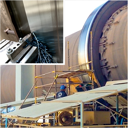
In-situ tyre machining at 3,5 rpm.
But even the best kiln alignment does not always last long. Temporary changes in production conditions, local material coating inside the shell, weather conditions, oil leaking from the roller housings, and an excessively dusty environment can all directly affect the axial movement of the kiln. However, it is a more important and permanent issue if the tyres and rollers are worn out over time and their contact ratio, and therefore their contribution to the kiln’s axial movement, is changed. At some point, the tyre/roller contact area may be reduced to 4 –5 cm and skewing the roller may change nothing or a great deal, depending on the roller surface form. On the other hand, all of the load will be carried on this very limited area and will damage the contact surfaces drastically.
Machining and grinding the tyres and rollers onsite, while they are mounted on the kiln and continuing production in normal operating conditions, is the key to avoid the production loss and the cost of removing all of these items, carrying them to and from a workshop, and re-mounting them. With the help of patented mobile equipment, Özek Makina professionally machines onsite during production to eliminate the deep and uneven surface defects and grinds to a high-quality final surface.
The main benefit to machining the tyres and rollers is that the relation between these surfaces, which become ideal cylinders, returns to the design values.
Any elliptical or wavy deformation on the circumference and surface forms in a concave, convex, or conical shape will be removed via machining and the result will be a much better tyre/roller relation with an increased contact ratio and reduced mechanical stress on the surfaces that are in contact. Therefore, the skewed roller will react as desired.

Tyre/roller surface forms.
Experienced supervisors should keep observing the kiln’s reaction to the changes on the diameter and the surface forms in order to realign the kiln when needed.
On the other hand, the lateral surface of the tyre and the thrust roller that are in contact might be machined and ground if an excessive load is exerted on the thrust roller which can damaged these surfaces and cause an even worse relation.
Summary
The rotary kiln is the heart of the cement production process and operates under the influence of huge loads and extreme temperatures. Observing the kiln using live sensors with real time data and periodic inspections with a highly detailed scope of measurements will enable plant managers to catch the problems before they stop production.
Özek Makina carries out professional rotary kiln services with highly experienced and skilled teams to enable cement plants to continue production and extend the service life of their rotary kilns.