Published by World Cement Magazine June 2021 issue.
World Cement Magazine has been published since 1928. It is the leading monthly trade magazine covering the cement industry and circulated globally to an ABC-audited circulation of over 5000 key industry decision makers.
Zeki Ozek, Ozek Makina Rotary Kiln Services, Turkey offers some insight into maintaining rotary kilns in a cement plant.
Cement production is a constant task that continues for decades with increasing quality and quantity goals. So keeping the equipment maintained to carry that load is the fundamental for that sustainability.
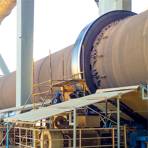
As we all know with our hard learned experience; a rotary kiln is a device to calcine and transfer thousands of tons of raw mix from feed inlet to outlet. The mechanics of a rotary kiln is actually quite simple. A large tube to carry the material, refractory to protect the tube shell from that enormous heat, tyres to hold the tube, chairpads to protect the tyre and shell from the thermal expansion issues, rollers to carry the whole weight, gears to rotate the system and slope to transfer the calcined material.
Keeping that simple mechanics under control when the size is that big and the temperature is that much necessitates a precise and experienced observation to understand the current condition. We may put these main tasks to our observation list as basics to keep the kiln rotating.
– Control the thermal expansion.
– Avoid excessive temperature and its deformation on the shell.
– Make sure all the piers are axially aligned and the load is distributed proportionally to the rollers.
– Check and control the axial migration of the kiln.
– Check the tyre and rollers’ surface form.
– Check the drive system.
Almost none of these headings are visible to the inexperienced plain eye and in most cases they are not predictable till they turn into a shut down issue. That’s why you need a professional hot kiln alignment service annually or biannually to take a technically detailed photo of your kiln that provides you a guide for preventive maintenance.
Hot kiln alignment.
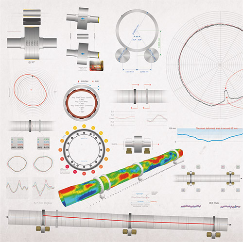
Visualisation of kiln inspection data.
Hot kiln alignment is the generic name of those detailed inspections and measurements in hot and running condition. A lot of mechanical inspection types and methods might be added to that list but we will discuss the most important ones here.
Basically the whole weight of the material, refractory, shell, chairpads, tyres and girth gear is carried by the supporting rollers. So it is important to distribute the load to all these rollers proportionally depending on their designed position and current condition. Any capacity increase over the time will change the weight, the sintering zone and the thermal expansion as it happens in most of the kilns. The tyre and roller diameters change over time due to excessive wear, changed thermal expansion or replacement. Probably some minor or major roller skewing or repositioning actions also took place in maintenance history. So understanding the current situation precisely is a must before taking any preventive action.
Axial deviation of ground fixed elements.
The kiln might be seperated to three sections at this level. The ground fixed elements such as rollers, bearings, drive units. Rotating elements such as shell, tyres and girth gear. And the relation between these fixed and rotating elements under the excessive temperature circumstances.
Theoretically we have a virtual triangle between the geometric centers of the tyre and rollers at each pier. Measuring the tyre and roller diameters and distance between the roller centers precisely helps us to determine the exact projection of the tyre center over the roller center line. We may easily find out any axial deviation by combining each pier’s triangle. Any diameter, height or slope difference between the rollers, any height difference between the tyres and any elevation difference between the piers should be carefully added to this calculation and interpreted carefully with remarkable experience. Actually here it is the most complicated chapter where half a millimeter may turn everything upside down.
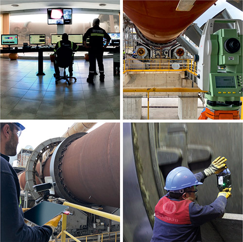
Several measurement setups.
The surface form of the tyres and rollers are also determined during the diameter measurement section so we know which rollers are conical and which ones are concave from now on. This is also visible at the contact surfaces of the tyres and rollers. We may judge the tyre/roller relation with the information of the roller skew, kiln slope, independent roller shaft slope and their accordance.
All these inspections lead us to check the actual position of the roller inside the bearing. This is simply visible under the housing inspection port. The gap between the bearing and the thrust disc and its side indicates the roller’s position and its duty at the axial movement of the kiln.
At this point, we have information about the position and condition of the fixed elements. We may relocate the rollers to the required position and remove any axial deviation. We may solve any bearing temperature issue by skewing the roller and gaining bearing/thrust disc gap or solve the shaft/bearing relation issues. We may arrange the independent roller slope issue by simple shimming under the housing. Any axial deviation or mislocated support in other words may lead to excessive tyre and roller wear, surface and/or shaft cracks or even shell crack in long term if left that way.
But are we allowed by the rotating parts? Is there any change in their plastic form? Are they really rotating around their geometric center?
Thermal expansion of rotating parts.
The heat that is transferred to the shell may reach up to 450°C at around the sintering zone. The shell flexion may erode the refractory lining as a result of gravity that may end up with a brick fall down and cause local hot spots directly on the shell. The refractory may get thinner over time and therefore the shell temperature may increase or the material coating may reduce it locally.
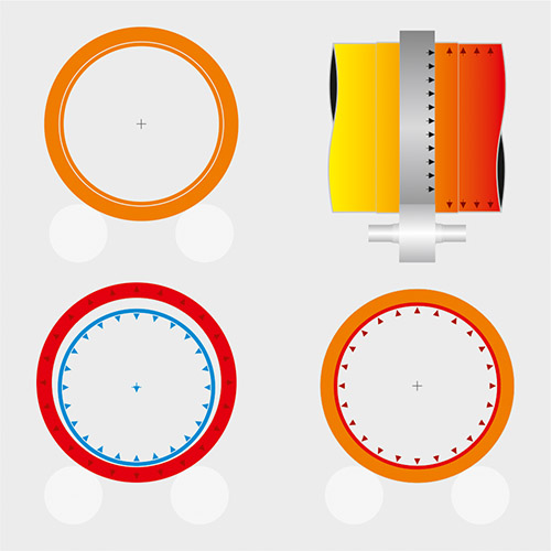
Several thermal conditions.
At 400°C, the shell loses 50% of its tensile strength and, over that temperature, shell distortion is permanent. The overall issues at the heat distribution may end with a thermal crank of the entire shell or even further turn to a mechanical crank when combined with axial deviation and excessive stable temperature.
The goal is conserving the requested heat distribution over the entire shell which is used to predict the thermal expansion and calculate the required air gap between the tyre and chairpads. Actually that gap and the tyre creep caused by it is your main inspection spot along with the thermal scanner data to understand the ongoing thermal issues. The creep of the tyre is the easiest indicator to observe. Low creep value indicates less air-gap that leads to a tight tyre/shell relation. We may assume that the shell is over expanded due to excessive temperature and/or misuse of cooling fans. For example over cooling the shell will increase the gap while over cooling the tyre instead will reduce it dramatically. Any mislocated cooling fan which can not separate where to cool will lead to unimprovable plastic deformations and even further to tyre cracks. The operator should be sure about proper cooling and cooler position. However, an excessive air gap gives room to the shell for more flexion (ovality) and therefore more motion and wear at the shell section welding and refractory. Uncontrolled thermal expansion may change the tyre diameter dramatically and may lead to axial deviation and its mentioned damages easily in mid term.
The shell itself is a long large steel tube and it behaves just like a balloon full of water under uncontrolled thermal conditions. Most of the kilns are supported at every 20-25 m and the sections between these support piers are alone against the gravity. So the bending is an inevitable result of long term running and it may get worse by the help of shell corrosion, material coating, torsion caused by the gear, lost tensile strength and turn to a mechanical crank. The shell rotates just like a crankshaft in that case and keeping the fixed elements at proper position is not enough alone. The root clearance of girth and pinion gears may change dramatically in one whole rotation. The load at the roller may change in a rotation and shift between the rollers of the same pier and that may even lead to a non-rotating roller in some cases. Keep in mind that a non-rotating roller also means a double loaded stablemate roller.
At Özek Makina, we laser scan the whole shell and get a real time 3D model of it to determine the plastic form, rotational behaviour and mechanical crank. That detailed scan gives us a quite useful 3D animation which we also provide to the client to calculate and judge the shell’s effect on the dynamic load changes which rollers have to face. That data is also confirmed by several other inspections such as roller shaft bending. It should not be forgotten that shell/tyre relation is very important at this point that a tight mounted tyre behaves rigidly along with the shell and transfers all that dynamic load to the rollers; however a loose one will let the shell’s crank motions be damped inside.
This much detailed scans and inspections will help a lot at preventive maintenance of minor issues. But when it comes to an over deformed, cranked or corroded shell it is just a clarification of the known with details of shell sections to be replaced and where to cut. An overdeformed shell may easily lead to roller shaft cracks, tyre/roller surface cracks and refractory issues which cause unexpected annoying kiln stoppage.

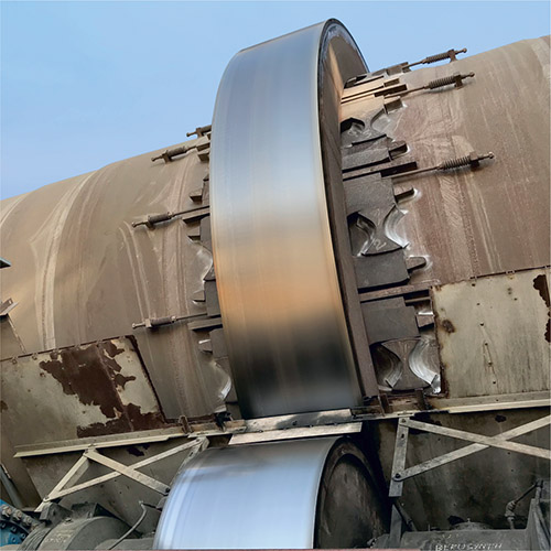
Tyre/roller surface forms.
Tyre and roller relation.
Determining the position of the fixed elements and the form of the rotating elements is a tough but enlightening task that lets you understand the current kiln behaviour in numbers clearly. But a rotary kiln is located with a slope for easier material flow and more importantly it is not holded by any fixed apparatus. If we keep all rollers unskewed (parallel to the kiln and tyres) the kiln will go all the way downhill.
We have thrust rollers to stop it but these rollers should actually be used as the last punch. So we skew the rollers precisely to avoid excessive uphill or downhill force, keep the tyres in its place and arrange the axial migration of rotating parts.
A hydraulic thrust roller is an important tool to understand and follow the necessary load to push uphill and arrange the roller skew from time to time.
Roller skew / alignment.
Roller skewing for kiln alignment.
The roller is designed with a shrink fit combined shaft. In most cases there is also a thrust disk but this is hidden under the hood, inside the housing. We may use the distance between this thrust disk and the bearing as a measure of the roller’s effect on the axial migration of the kiln. Most housings have a cover to check the shaft and lubrication, which should be kept closed to protect the bearing and the shaft. Once you open this cover, you will notice that the thrust disk leans on the bearing and is not lubricated well or there is a gap between them. Depending on the design, that thrust disk might be on the outer or inner side of the shaft.
Let us say you see the tyre rotating uphill when you stand across the kiln facing the tyre. The maintenance team highlighted excessive temperature at the downhill bearing. You have opened the cover and noticed that there is no gap between the thrust disk (which is located on the inner side between the bearing and the roller) and the bearing. The thrust disk is forcing the bearing downwards during its downwards movement attempts, which damages the disk and heats the bearing and the oil. That disk is actually helpful, as it would be worse if you had only noticed the situation once the roller was completely out of its housing.
When you face the tyre, if it is rotating up, the roller will also leave the pushed bearing behind. If the tyre is rotating down, the roller will also come to the pushed bearing. By pushing the downhill bearing in, the roller will move uphill and increase the gap between thrust disk and the bearing, solving the problem. (Keep in mind that if the thrust disk is located on the outer side, that attempt will reduce that gap and increase the temperature even higher.) A domino effect The shell always moves in the opposite direction to the roller. In our case, the roller moved uphill when we pushed the downhill bearing in, so the kiln started to move downhill. Now you are at a point where you need the hot kiln inspection report. Some of the rollers were already at the limit of their bearing/thrust disk relation and were starting to increase the temperature. Perhaps the load on the thrust roller has been increased or reduced, or a conical or wavy roller started to move downhill with the kiln.
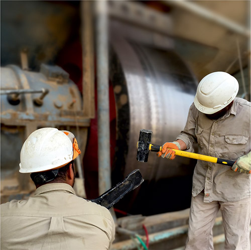
Tyre and roller surface machining and grinding.
In-situ tyre machining at 3,5 rpm.
Reduced tyre/roller contact is the corollary result of that compulsory roller skew. And that leads to more wear on the contact area. So the process to a conical tyre or roller starts. That wear increases the contact and necessitates additional skew and it goes on.
At some point you decide to change your whole kiln alignment and the same wear starts on the other side of the roller. We may mention lots of variation on the scenario but in most cases the loop ends with very limited tyre/roller contact where all the load stress is carried by only a small portion with lots of surface cracks. Moreover any additional skew does not affect much since the contact is gathered mostly in the middle.
Once you resurface the tyre and the roller as a set, you increase the contact between tyre and roller, clean out the horizontal waves that cause vibration and the vertical waves that lock the roller to the tyre during the axial movement.
It is completed once the pier is again aligned to balance the reduced diameter.
Final surface of tyre and roller.
Now you are ready to arrange the roller skew and let the whole kiln migrate axially in desired limits.
Depending on the wear level, material, and the finish requests, grinding or machining with late bid might be chosen separately or together for resurfacing.
Sure, the speed of the kiln during resurfacing services should not affect your production but your production needs should also not affect the final surface quality.