Published by World Cement Magazine February 2017 issue.
Zeki Ozek from Ozek Makina Rotary Kiln Services, Turkey, offers some insight into maintaining rotary kilns in a cement plant.
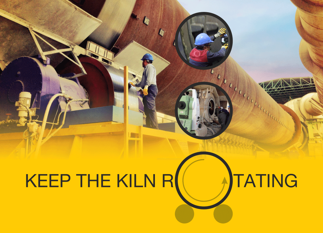
A rotating kiln in a cement plant is the same as a beating heart in our body. That is why we all work hard to keep the kiln rotating. It is there to calcine every individual particle in thousands of tonnes of raw mix. This necessitates rotating and heating the material inside a drum, designed to carry this huge load and stress, which is rotated on rollers inside a bearing. Heating the material to 1450°C will therefore also heat the shell, despite thick refractory brick lining. A thicker ring is then required to hold the shell and rotate it over the rollers, while leaving the tyre free to prevent it deforming the hot shell.
The usual suspects
The shell flexes and erodes the refractory lining as a result of gravity, causing a brick to fall down. The extreme temperature needed for calcination affects and deforms the shell. At 400°C, the shell loses 50% of its tensile strength and, over that temperature, shell distortion is permanent. This local distortion may reshape the shell or crack it which effects the load distribution and energy consumption.
The tyres and rollers wear over time, depending on their contact form. Even the pier itself slowly degrades.
The kiln’s axial movement schedule and the load over the thrust roller changes due to uneven wear on the tyre and roller surfaces.
These natural forces can be stopped before they develop into problems by:
• Keeping the bearing temperature stable.
• Changing the bearing oil regularly.
• Keeping the roller load distribution equal.
• Keeping the kiln’s axial movement schedule live.
• Keeping the tyre’s creep and clearance stable.
• Keeping the shell temperature stable.
• Lubricating the gear, roller and tyre bore regularly.
Walk around your kiln daily
The CCR team usually flags issues concerning bearing temperature, visible red spots on the shell, thrust roller failure and high vibration on girth gear. However, all of these problems occurred step by step.
A daily kiln walk is key for preventive maintenance. You can log and analyse shell temperature, bearing temperature, tyre creep, the kiln’s axial position and many other measurements using sensors but seeing the
situation with your own eyes makes you an expert on your kiln. Logging your basic kiln checks helps you to analyse ongoing problems and find an early solution.
Your daily kiln walk will help you to identify problems, including:
• Product leakage and wear on seals.
• Visible hot or dark spots and deformations on shell.
• Visible cracks on the welding joints of the shell.
• Cooling fans.
• Simple chalk-check for tyre migration.
• Root clearance between pinion and girth gear.
• Gear lubrication.
• Vibrations of pinion, thrust, bearings and piers.
• Pressure and vibration on hydraulic thrust roller.
• Roller and tyre surface wear.
• Contact pattern of thrust, rollers and tyres.
• Chair pads under the tyres.
• Bearing lubrication efficiency and shaft condition.
This simple check-up relies on visual observation and experience. You may decide to take some preventive action when you merge your observatory results with real-time sensor readings.
At the end of the day, your findings will highlight the developing problems but you will still need more comprehensive information to take action.
Hot kiln alignment
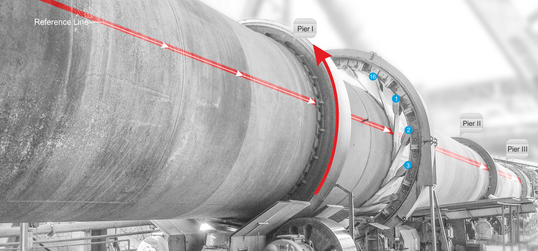
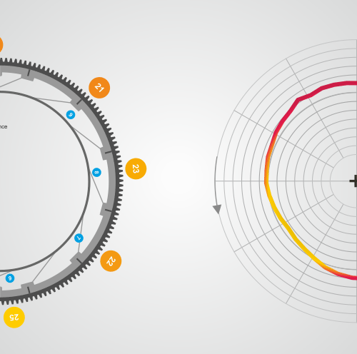
For a huge steel tube at up to 450°C, thermal expansion changes all measurements. Even if all the rollers are in their correct positions and are keeping the kiln on the center line, the deformations and cracks on the shell create eccentric rotations and change the load distribution. The easiest way to understand this is to check the root clearance of the girth gear over a whole rotation. You will see that the clearance increases step by step every 30° and then reduces again. The mounting springs, shell crack and the misaligned rollers share this problem. The gears are visible but the load change on the rollers is not that easy to understand and mostly visible with a cracked shaft.
The kiln can be divided into three sections discussing alignment:
• The position of the fixed elements such as rollers and the pinion gear.
• The position of the tyres and the girth gear over these fixed elements.
• The position of the shell.
The rollers are located equally from the centreline. The distance between two roller shaft centres of the same pier should be equal to the sum of the radius of the tyre and roller of the same pier. That creates an equilateral triangle with a 60° operating angle that distributes the load equally across both rollers.
The slope of the kiln determines the elevation of the piers and the height of the rollers depending on the diameter of the tyres, rollers, height of the chassis and the overall slope of the kiln.
During this inspection it may be discovered, for example, the middle pier’s elevation is higher than the virtual centerline. Therefore the load on the middle rollers is greater than required. Or maybe one of the rollers is closer to the centreline by, say, 3 mm. In this case, this roller is carrying more than the other.
In most cases, your earlier complaint matches the measurements and the measurements clearly show how far to adjust the roller.
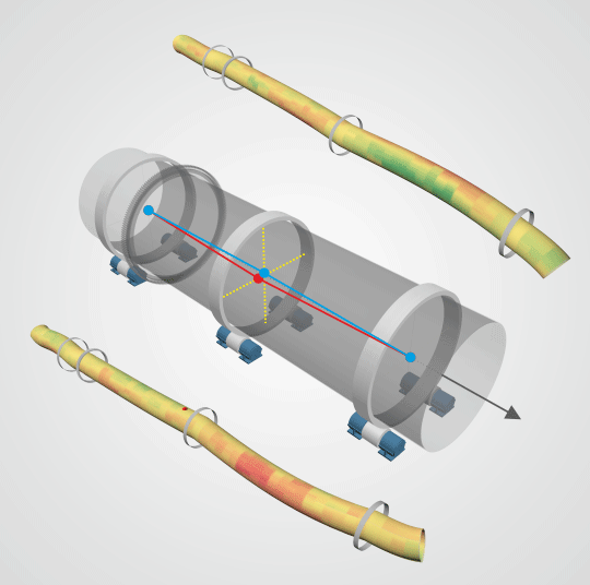
Once all the measurements are analysed together, the shell can be scanned and the deformation and the eccentricity caused by the crack can be visualised.
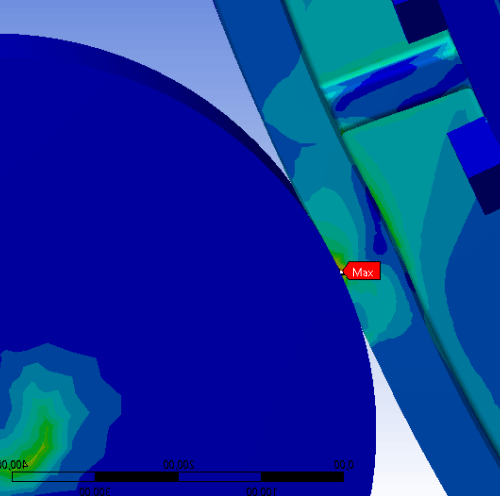
Having information on the diameters of the tyres and rollers, as well as their surface profile (concave, convex or conical), the positions of rollers and the shell’s shape, the dynamic roller shaft flexion data, and the gear root clearance change in a rotation means that the kiln can be simulated on a computer and the visual observations can be compared with ongoing complaints.
Some of the issues mentioned above are mostly related to the thermal distribution over the shell. For example, if you have a coating ring inside the shell, it will keep the remaining hot material inside more than expected. Therefore, the shell will be hotter and naturally expand more. If this happens around any pier, you will notice that the tyre stops migrating. The non-migrating tyre is the visible part of the iceberg. In fact, the expanding shell is forcing the tyre to expand with it but this leads to a deformed shell and cracked tyre. Meanwhile, the tyre also expands and the whole thermal issue lifts that pier up, forcing the rollers and shafts under it to carry a huge load.
On the other hand, if the shell flexes due to gravity, this flexion should be in a range depending on the shell diameter. If the shell is corroded and the gap between tyre and chair pads is excessive, then the shell will find more room to flex and that flexion will wiggle the bricks under it. In each flexion, the bricks will open and the material will fill in. Then the bricks will try to close but will not succeed and the stacked material will break the tops of the bricks. Then you will have thinner refractory and a more heated, expanded shell and again a non-migrating tyre.
In reality, the kiln is a live thing. Nothing stays static in a rotating hot kiln, but some aspects change more slowly than others. The foundation sinks around 1 mm per year depending on the ground quality but the shell may expand 10 mm in an hour if it has a thinner refractory or an excessive coating inside.
Just as when we visit the doctor we tell them our problems before they start their examination, so should the procedure for a kiln be the same. You should describe what is happening and share your logged data. The inspection is mostly done to determine the cure.
Axial migration
The kiln is designed with a slope to push the calcined material downhill to the cooler, supported by thrust rollers. As such it is important to keep the rollers and the lateral sides of the tyres unworn.
The best way is letting the kiln hold itself. In a common three pier kiln, six rollers do this job. The skew of the rollers determines their effect on the kiln’s axial migration. They do nothing when we locate the rollers parallel to the tyre. We call this situation neutral and use it primarily for the middle pier, while using the remaining rollers as thrust to push the kiln up together with the real thrust roller. The total thrust should be equal to the neutral force of the kiln caused by the slope and should be shared proportionally to keep pressure on the thrust roller’s hydraulic pump around 70 – 100 bars.
If your kiln is climbing up when the rollers are dry and moving downhill when you lubricate any of your rollers then we may judge the kiln as normal but in most cases you should not need to lubricate the roller surface.
Understanding the roller’s effect on the kiln’s axial migration?
The roller is designed with a shrink fit combined shaft. In most cases there is also a thrust disk but this is hidden under the hood, inside the housing. We may use the distance between this thrust disk and the bearing as a measure of the roller’s effect on the axial migration of the kiln.
Most housings have a cover to check the shaft and lubrication, which should be kept closed to protect the bearing and the shaft. Once you open this cover, you will notice that the thrust disk leans on the bearing and is not lubricated well or there is a gap between them. Depending on the design, that thrust disk might be on the outer or inner side of the shaft.
What does It mean?
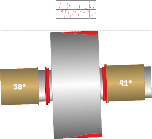
Let us say you see the tyre rotating uphill when you stand across the kiln facing the tyre. The maintenance team highlighted excessive temperature at the downhill bearing. You have opened the cover and noticed that there is no gap between the thrust disk (which is located on the inner side between the bearing and the roller) and the bearing. The thrust disk is forcing the bearing downwards during its downwards movement attempts, which damages the disk and heats the bearing and the oil. That disk is actually helpful, as it would be worse if you had only noticed the situation once the roller was completely out of its housing.
Forget the old rules
When you face the tyre, if it is rotating up, the roller will also leave the pushed bearing behind. If the tyre is rotating down, the roller will also come to the pushed bearing.
By pushing the downhill bearing in, the roller will move uphill and increase the gap between thrust disk and the bearing, solving the problem. (Keep in mind that if the thrust disk is located on the outer side, that attempt will reduce that gap and increase the temperature even higher.)
A domino effect
The shell always moves in the opposite direction to the roller. In our case, the roller moved uphill when we have pushed the downhill bearing in, so the kiln started to move downhill.
Now you are at a point where you need the hot kiln inspection report. Some of the rollers were already at the limit of their bearing/thrust disk relation and were starting to increase the temperature. Perhaps the load on the thrust roller has been increased or reduced, or a conical or wavy roller started to move downhill with the kiln.
Determining the rest
A 4 rpm tyre with 6500 mm diameter, would move around 43 000 km per year if it was free.
Since the tyre and the roller are rubbing against each other all the time, it is impossible to stop the wear despite the graphite lubrication or best quality steel used for them.
A concave, convex or conically worn roller and tyre determines the axial movement of the roller and therefore the axial migration of the kiln. Moreover, most rollers and tyres are worn in a vertical wavy form that locks them together and lets the roller move axially together with the kiln. Once you push a bearing in, to reduce the temperature, you let the other worn rollers move with the kiln and create other problems.
On the other hand, a conical roller also behaves independently from its skewed position in most cases.
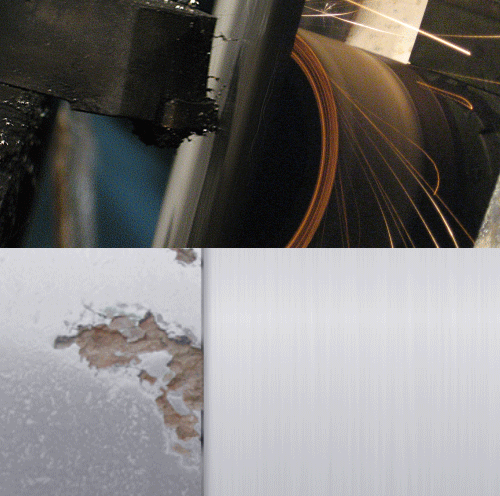
Resurfacing is the solution
Once you resurface the tyre and the roller as a set, you increase the contact between tyre and roller, clean out the horizontal waves that cause vibration and the vertical waves that lock the roller to the tyre during the axial movement. It is completed once the pier is again aligned to balance the reduced diameter.
Now you are ready to arrange the roller skew and let the whole kiln migrate axially in desired limits.
Depending on the wear level, material, and the finish requests, grinding or machining with late bid might be chosen for resurfacing.
Sure, the speed of the kiln during resurfacing services should not affect your production but your production needs should also not affect the final surface quality.
